Shape the deep end carefully, over-excavating 3" to
4" to allow
for concrete/sand/vermiculite bottom. Try to have the hopper bottom finished to the
diagram dimensions or no more than 1/2" deeper. The liner is designed to fit
your pool dimensions. The liner can stretch even if you are out by more than
an inch but if you happen to have a tile border liner circles may look like ovals.
If an inwall step is to be installed dig about 3' extra (6' total) where
the step is to be installed to leave room to work with the step.
If a high water table is expected the deep end should be dug first to determine
the height of the water. If severe, the pool may have to be raised to avoid troublesome
underground water or a sump hole may be required. Consider delaying ordering
the liner if you suspect you have a high water table.
Ground water is the term used for the water table. If you
should encounter ground water while digging the hopper, do not
panic. Simply follow these simple recommendations:
1. Over dig just the bottom of the hopper by 1' to 2'.
2. Put a 5-gallon pail in the middle of the hopper.
3. Use pea size rock to bring the hopper back to grade. If
there is an excessive amount
of water you can run a big O-drain around the
outside of the hopper and into the pail.
4. Run a plumbing line from the pail in the hopper to near the filter.
5. Pump out the water in the hopper while finishing the pool until the
liner has been
dropped and the pool is full of water.
6. When installation is complete, cap the plumbing line, leaving it
available for use
in the future, should the liner need to be replaced.
7. Once the pool is filled with water the water pressure should keep the
water from
floating the liner.
An excavator or Drott is the best equipment with which to excavate your pool.
Generally the larger the machine the easier it is to excavate the
pool. Have the operator of the excavator study the drawings of your particular size pool. Make sure he/she understands the
tolerances for the pool walls and inside finish. An accurate job will simplify your
installation.
During the period of excavation, a person with a shovel should work in the
hole (not when excavator is working),
grading and making periodic checks on all measurements to ensure accuracy and eliminate
unnecessary hand digging later. Depth may be checked by transit or measuring from a cord
tied between the grade stakes.
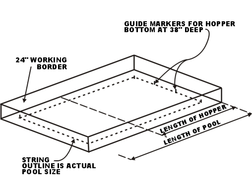
FIG. 6
WARNING:
Make sure excavator doesn't under-excavate or over-excavate the job.
The closer to the dimensions the operator keeps, the more correct the
shape of the hole, and the less hand labor you will have to do later.
Once again, careful checking with a transit, hand trimming and raking will
speed up the excavation and make it less costly for you and less work in the
long run. Establish points outside of the excavation and where
there will not be any excavated soil piled, so when
the initial part of the pool is dug you will have references to re-establish the
hopper and depth of the pool. Study Fig.6.
PHASE 2 - PANEL ASSEMBLY
Take a black marking pencil, chalk line or crayon and mark each panel
along its entire length 2" from the bottom. Since the sections are 42" high,
this line will measure the finished pool depth of 40" once the walls are in place and
pool bottom finished. Be sure not to go above this line when cement, sand or
vermiculite is later poured in the
bottom or the pool will be too shallow for the liner to fit.
Under NO circumstances should the steel walls be placed on recently
disturbed ground. A level foundation of undisturbed earth should be provided where the wall
sections will be installed.
Lay the steel panels on the grass, around the pool in the order you
chose in Fig.1. Place skimmer, inlet and light panels in their
correct order around the pool. Normally the welded side of the panel goes up. The
panels are reversible.
If steps are present, determine their location before starting panel assembly.
Place the steps in the shallow end so when you enter the pool from the steps you
step on to the flat surface of the shallow end (not partially on the shallow end
break). Brace the step to the proper height so
that the top of the step is level with the top of the coping. Clamp
the steps to the steel panels using C clamps or vise grips. Once the
steps are positioned correctly drill the holes that will be used to bolt the
steps to the panels. We supply step levelers but recommend
supporting the bottom of the steps with concrete
or concrete blocks. Ensure you do not have an abrasive material against
the bottom of the steps. Consult the manufacturer's recommendations
for the installation of the steps.
As the final hand trimming is being done, the wall panels may be
lowered into the working border and leaned against the side of the excavation.
One option to to lay a concrete footing for the panels to sit on.
If you
would like to make this footing (optional), here is a chart that tells you approximately
how many yards of concrete you will need for your pool's footing.
NOTE: Take a sight through a transit or use the longest spirit level available
to be sure the concrete will be level at the depth you want.
| Pool Size |
Needs |
| 12' x 24' |
Approx 1 square yard
of concrete |
| 14' x 28' |
Approx 1 square yard
of concrete |
| 16' x 32' |
Approx 2 square yards
of concrete |
| 18' x 36' |
Approx 2 square yards
of concrete |
| 20' x 40' |
Approx 2 square yards
of concrete |
The footings are framed with 2 x 4's, standing on edge, and the footing is
made approximately 1' wide. (See Fig.7).
The strings that were used as pool outlines should be placed between
the corner stakes (as in Fig.6) and will now guide the positioning and square placement of
the footings or wall sections. If not laying a footing, patio stones can be used at each panel joint.
Place pegs to help position the bottom of each panel along
a straight line so the panels won't slip in toward the pool at the bottom.
The 2" x 4" framing should be dug down 4", otherwise your pool height will
be 4" higher than you expected.
FIG.7.

When you are ready for the panels, put the stairs in place (if applicable)
and start at any corner, going both
ways (this way the panels will be self supporting). The panels can now be bolted together
as you go. An end view of the panel can be seen in Fig.7. When
assembling the panels start at a corner and work in two directions.
Note: The rectangle's
top and bottom lips are 5" and the shapes have a 5" top lip and
a 3 1/2" bottom lip.
If you aren't using a footing, patio
stones should be dug into the ground at each panel joint to give the panels a
level footing to sit on. We recommend using a patio stone at each
joint. Shoot each patio stone with a transit level to ensure they are they
are at the correct height. Make sure each patio stone is
level. Shave the high spots under the blocks.
Ensure the panels are lined up to one another, flush on the
inside and top of the pool. Stabilize each brace to ensure they do not move
when concrete is poured. ( Normally one A brace at each joint).
If you are using a deck support system there is a brace at each joint and one in
the middle of the panel if the panel is 6' or greater.
If you are going to install a concrete deck there are two options for deck
support. You can use our deck bracing system or sonar
tubes. The sonar tubes are supplied by concrete
companies. To get the deck support using the sonar tubes you need to
place these tubes about every 4' around the pool. Pour concrete into
the tubes and they will provide the support on the outside edge of the deck.
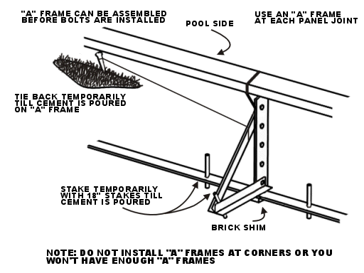
The "A" frames fit together as in Fig. 8.
Take a sight through the transit as each panel is joined to see that
the level of the pool is maintained. If no transit is used maintain the level by checking
with the longest spirit level available. Even if you have a concrete footing check the
level of your panels.
After steel panels are assembled, square the pool by obtaining equal
diagonal measurements from outside corner to outside opposite corner of the pool. Check
the level again.
The "A" frames or Deck braces can have a cord tied around
them and staked back for squaring purposes as in Fig. 8, until cement is poured.
Stabilize each brace to ensure they do not move when concrete is poured.
Be sure to add A frame assemblies as each panel is added. Never
tighten bolts until the inside surfaces are flush. For deck brace
system assembly cut and paste this link into your
browser.
Once you are positive your panels are square and level, fix the
position by driving a steel re-bar through one hole in the base of an end
section of the panel, or concrete spikes into the concrete footing. Staking rods are
driven down to within 3" or 4" from the end. One stake
is required at each panel joint. Put the stake into either panel at the
joint.
Place framing boards in the hopper base to form the bottom of the deep
end. Be sure the tops of these boards and drain will be at the finished bottom
depth. Pour concrete to 2" below the top of these boards (see
video).
The purpose of a main drain in a liner pool is to aid re-circulation of
the water in your pool. It is hooked into the suction side of you
pump. It should be installed in the middle of the hopper at
the lowest part of the pool. Cover the entire top of the main
drain, screw holes and entire top outside perimeter with duct tape to ensure
dirt does not get into the main drain during bottom preparation.
Dig a trench up through the side of the hopper to accommodate the main drain
plumbing line (a
main drain is not required with an AquaGenie). Run the pipe from the main drain,
up the side of the hopper, under the wall and then to the pump
house.
When pouring the concrete for the hopper bottom the main drain may
tend to float in the concrete. Make sure it does not rise above the finished
bottom depth. Wet and tamp all loose earth in the bottom of pool.
Pour the concrete 2" below the top of the hopper form. The top
of the hopper form should be at the level that will be the finished grade of the
pool hopper.
If you are using an AquaGenie it is not necessary to install a main drain.
Again re-check walls and corners for level, alignment, and squareness.
Once concrete is poured adjustments will be impossible.
For approximate concrete required see chart below.
| 12 x 24 |
2 Yards Cement |
| 14 x 28 |
3 Yards Cement |
| 16 x 32 |
4 Yards Cement |
| 18 x 36 |
5 Yards Cement |
| 20 x 40 |
6 Yards Cement |
Smooth the concrete so it will make a better surface for
running the pool plumbing.
FIG. 10.

Pour 6" to 8" of concrete on the working border of
pool, covering the remaining steel stakes at the base of the panels, and the footing if
you used one. A hole of almost 2 sq. ft. by approximately 1 ft. deep should be dug to accommodate the end of each
"A" frame. The "A" frames are covered with approximately one wheelbarrow full of
concrete each and the anchor rods are re-inserted into the hole
in the "A" frame. This can be done at the same time you pour the
concrete border.
CAUTION: Be very
careful when you pour the concrete border below that you do not knock the wall out of
alignment. Concrete is very heavy so be cautious when placing the concrete ring
around the pool. Be sure when pouring concrete that any large
openings under the pool walls are filled.
Once the walls are up, check the depth in various sections of the pool
bottom and hopper in relation to the top of the walls. If the excavating has been done
carefully, the pool floor should be very near the exact depth and only a small amount of
hand trimming will be necessary.
As mentioned before, the depths may be made 1/2" deeper than
required but if your excavation and construction are accurate there is no need to do this.
The final sizing of the pool bottom governs the smooth future appearance of the liner in
the finished pool. In order to establish your hopper grades, first accurately locate the
bottom plate of the pool. Place four stakes, one at each corner of the hopper base and set
a string outline around these stakes at the proper depth for the pool hopper.
String guides can now be run to outline the four sloping corners of
the hopper, from the base of the panels to the hopper framing boards.
Check pool bottom before drain installation to ensure the drain is set at
the correct depth.
Section 3
PLUMBING AND FIXTURES:
Check the electrical codes as they will vary from one County to the
next. Pool plumbing lines can be made of poly pipe, flex pipe or PVC
(schedule 40).
All plumbing should be done before you start the backfill. The
pipe should lie on top of the concrete pad behind the walls. If the
concrete pad is rough put a few inches of sand over top of the concrete pad
prior to running the plumbing lines. Do not kink or
stress the pipe. Pressure test or run the pump and filter to check
for leaks prior to backfilling.
The amount of pipe and fittings will vary with the type
of plumbing installation that you choose. Once you decide on what you
need buy about 30% more as you can return them at the end of the project.
That will save you going to the hardware store if you need additional plumbing
fittings.
There are links to some
examples of plumbing layouts at the end of this manual. Install pipe
for the inlets using the same
pipe as you used for the drain to the skimmer. If you have 2 skimmers
run a separate line to the pump house for each skimmer and one from the main
drain. If you have one skimmer and a main drain it is recommended to
run a line from the skimmer and one from the main drain to the pump
house. If you are using the AquaGenie skimmer system run a
separate line from the suction of each AquaGenie and a separate line to each one
of the returns of the AquaGenie. If not completing the plumbing at
that point place a rag in the end of the pipe to keep it clear of debris.
Avoid kinks in the pipe and unnecessary
use of elbows which tend to hamper water flow.
To prevent a possible air lock, the suction line from the
pool to the pump should slope uniformly in one direction. The same uniform slope should be
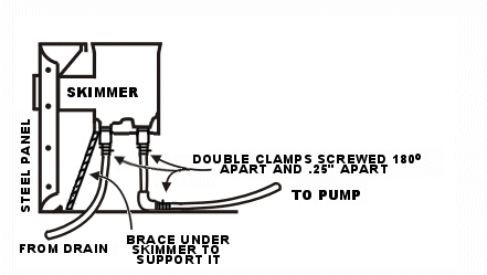
maintained on the skimmer line. (See Fig.11). Generally if your pump
and filter are more than 50' away from the pool you should consider 2"
lines.
Flexible plastic pipe is usually bent around pool corners
instead of using elbows.
Caution: If you are
installing a main drain we suggest that you install 2 main drains tied in with a
T as a safety precaution in case someone stands on one of the
main drains. In a number of Provinces, States and counties it is
against the law to only install one main drain. The main drain in a vinyl pool is mainly used as an aid
in circulation. A main drain is not required with an AquaGenie skimmer
system see http://www.northwestwholesale.com/aqua-genie.asp
To ensure the plastic pipe does not leak at the threads, wrap teflon tape on the threads
of the adapter and screw into the fitting, then put some plastic joint compound (optional)
on the other end of the adaptor.
If you are using poly pipe slip two stainless steel clamps (use
clamps with stainless steel or CAD heads) over the end of the
plastic pipe with the tightening screws of the clamp on opposite sides of the pipe.
Push
the plastic pipe over the serrated end of the adapter until it is well in place.
Tighten the clamps about ¼" from the end of the pipe and ¼" apart.
(See Fig.11). If it
is cold and difficult to insert fittings, you can heat the pipe with warm water to make it
more pliable before clamping.
Note: In cold weather areas if the frost goes below the footings of the wall (3
½') it will be necessary to support the pipe coming from the fittings. e.g. install
a 90 degree elbow and run the pipe to the concrete footing below - this will give the
inlet support and prevent the pipe from breaking the inlet.
FIG. 11.

If installing fiber optic lens assemblies they should be cut prior to starting
the bottom finishing as the metal filings could cause rust spots on the liner if
completed after the bottom was finished. The lens assemblies should be placed in
the long wall facing away from the patio area.
Run a 1 ½" conduit/pipe from each lens assembly to the location
where the illuminator will be located. The
illuminator can be outdoors. Try place the illuminator closer to the
lens assemblies as it is less expensive to move the
illuminator than to pay for the underwater cable. In the pool, mount the lens assembles 6" – 9"
below the water line. In the spa,
mount the lens assembly in the foot well. Follow the installation
instructions in the manufacturers manual. The illuminator
should be at least 10' away from the pool.
If installing a safety line the anchors for the safety line should be
installed 2" from the top of the wall.
FILTER:
Attach hose from skimmer to pump (see plumbing
diagrams). Hose from inlets should also come up
through the floor of your filter house. (See Fig.11). If you
have a sand filter fill
the filter tank with silica sand if using a sand filter.
IMPORTANT: Wire the pump motor with the proper amount of electricity.
A common mistake is to wire the motor incorrectly. In-ground pumps
are normally wired for 220 volts.
Filter and all plumbing should be completed and ready for operation before
liner installation. Even if the filter house is not built the filter can be connected. The
filter should be working before the chemicals are put into the water.
OXIDIZER:
When installing an Oxidizer a stand pipe is used in a new installation as
per the manual. It will not be necessary to install a check
valve. If a stand pipe is not used then it is necessary to install
the check valve. Normally the check valve is used when an Oxidizer is
installed on an existing pool.
Section 4 SHAPING, FINISHING AND BACKFILLING
There are four types of pool bottoms that are typically used:
l. Sand (thoroughly-washed mason sand - not recommended - last
choice).
2. Sand (thoroughly-washed mason sand) and cement (dry mix 7 - 1) - second last choice.
3. Grout/Mortar mix - washed sand (no stones) 3500 psi very heavy slump. Can be
obtained from your local cement company.
4. Vermiculite (which goes by various brand names) (see below).
You can get information on pool pad by Grace Bros. (CPBA) at http://www.graceconstruction.com/vermiculite/verm_contact.html
They can advise you of suppliers in your area. As
well, you can call Tim DeJarnette at 1-800-982-8009. They have a product
called Pool Krete. Mention North West Wholesale. Their website is www.strongseal.com
As well, check with local contractors for information on obtaining
the product.
Start in the deep end near the top of the hopper. Do not apply vermiculite/mortar
mix/sand cement mix above the (2" from the bottom) line you have marked on the panel. Work your way
up the slopes using a
trowel that has rounded corners. You may have to round the corners
of the trowel by grinding
them off. A trowel with rounded
corners is easier to use than a trowel with square corners. The shallow end can then be trowelled
and finished.
A wet trowel sometimes works better. Remember, the liner will
appear as smooth as the surface you make on the bottom. Review manufacturer's recommendations for
mix and type of mixer to use as they may vary for the various products.
A mixture of vermiculite and cement can be used. This
varies from manufacturer to manufacturer so this formula is a guide
only. For the Grace Brothers product call Pool Pad use a paddle mixer and mix 4 cu. ft. of vermiculite to a half
bag of Portland (review manufacturer's recommendations for mix as they may vary
for the various products).
A dry cement/sand mixture can be used for the bottom
and the ground moisture will eventually make the mixture hard. We do not
recommend using sand only mixture or a dry mix of sand and cement for the bottom
of the pool. We recommend the
Vermiculite or a Mortar/Grout mix mentioned previously.
LIGHT:
Check to see what is required by local electrical codes for an underwater
light. The light can be purchased with or without a conduit.
If the light is purchased without a conduit check you local building codes to
see if a PVC conduit can be used. When you use PVC as a conduit ensure that all the light components
are bonded. When putting the conduit into the niche you should use a
sealant such as Permatex or Plasto Joint Stick.
GROUNDING
Grounding of all pool components is essential and normally required.
Check your local building codes as they will vary from place to place. Use
an electrician for all electrical work.
BACKFILLING:
Backfill is done after the plumbing and should not contain clay and absolutely no large rocks. The bottom layer of backfill should be porous material
to allow proper drainage away from the back side of pool walls. This layer of backfill
should come up just above the plastic piping coming from the inlets.
Consider pressure testing your lines or wait until your filter is hooked up and
you can test the liners before burying the lines. I you have installed an
AquaGenie you will only have one trench and the lines going to one location.
We recommend using pit sand or similar material for backfilling.
Section
5
COPING AND LINER:
The coping supplied with your pool is different than that in the
video. The video coping is a 2" single track and we are
presently supplying a 3" dual track with one of the tracks used for fiber optic
lighting. The installation is basically the same with a few
variations. Use the video as a guide but follow the instructions in
this manual. There are two types of coping which are shown in the photographs:
- Retainer strip coping
- Bull nose coping
RETAINER STRIP COPING – is used if concrete coping, redwood deck, carpet,
flagstone, or patio stone is desired for a pool deck. It is installed flush with the
inside of the pool with the groove facing toward the water. It is fastened with # 10
– ½" Phillips self-tapping screws, spaced with 6" centers.
ALUMINUM BULL NOSE COPING– is set upright on the front edge of the steel
panel. It was designed to act as a form to pour concrete up to. Tape seam between coping
and panel to prevent concrete from going in between. If the coping
is not already notched you can notch everything but the face
of the coping every ¾" and it will bend around the corner of the pool. (See
Fig.12).
Pre-bent corners are supplied with 2' radius corner pools. The
inside corner on a square L is not supplied as it is not difficult to
bend. There are no pre-bent corners supplied on 4' radius pools as
they are easy to bend.
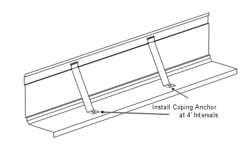
There are coping stabilizers included with the coping kit. They
are used at each joint and every 4'. They are used to stabilize the coping at the
joint and can be used to push or pull the coping in place. They are to be screwed to
the wall. As well, coping joiners are available. They
must be installed in the ends of the coping.
To cut the coping place the coping face up. If you are
using a power miter box (chop saw) use a carbide tip blade and at least 40 tooth
blade - a
60 tooth blade is preferable. Put WD 40 on the area you are going to cut.
Putting the coping face up will prevent burring on the face as the burr
will be on the inside.
If installing the coping on a Grecian pool, cut the coping from the
back but not all the way through to the front face of the coping. It will
then bend around the corner.
To install coping on the square L reverse corner remove every second tab
at the back of the coping. Gently put the coping into the corner.
Installation of Preformed Corner:
Push the
center of the corner snug to the pool wall. Secure the center of the corner with
the self drilling screws. Install screws moving to the outside ends of the
corner.
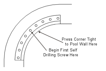
Begin installing straight pieces of coping on
the ends and sides of pool. It will be necessary to cut the last piece of coping
to fit on the ends and sides. Make sure that the ends of the coping are aligned
with each other, secure the coping with self drilling screws at 8" intervals.
Install coping braces crossing each joint of the coping and space the braces at
4' intervals.

SHAPED POOLS:
Begin installing coping at the step if the pool has a
step. When the pool has no step begin installing on the largest
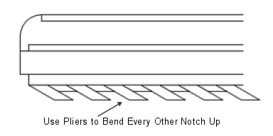
radius. When you come to a reverse radius using pliers bend every other notched
piece upwards around the reverse radius as per diagram.
FIBER OPTIC ROUGH-IN INSTALLATION:
To install the conduit for fiber optic coping run a 1 ¼"
conduit/pipe from the coping to the light source. It should be attached to the wall so if the ground
shifts you will still be able to feed the fiber optic cable through the conduit.
There are many ways to attach the conduit to the wall. One way would
be to drill 2 holes in the top of the wall and put 2 bolts or screws into the
wall and then wire or tape the conduit to the bolts or screws so it cannot
move. We are supplying a small piece of 40 strand cable with each kit so you
can see the size of cable that has to be run through the conduit.
The cable can be run in one side of the
step and out the other.
The cable is not meant to go around the step so if
it cannot go into the coping on one side of the step and out the other then it
should go under the step. If you do
this, keep in mind it should be put in a conduit.
The back of the step is not made for the cable but
it is possible to put a slot in the concrete at the back of the step so the
cable can go around the step. You
will be able to gauge what is required when you see the enclosed cable sample.
Keep in mind that the perimeter cable must be a
continuous loop. It goes from
the illuminator to the pool, around the pool and then back to the illuminator.
The shorter the cable the brighter the light.
The illuminator should be at least 10' away from the pool unless it is
behind a wall.
If you want to see what is involved to install fiber
optic lighting please go to http://www.northwestwholesale.com/PDF-Documents.asp
and click on the Hayward Fiber Optic Lighting Installation Manual.
It is a large document so it will take a while to load.
There is some good reading in fiber optic layout and installation in this
manual.
Vinyl liners should be stored in areas with temperatures above 50 degrees
F to prevent excessive shrinkage and permanent folds in the vinyl.
If the liner is to be installed in cool weather keep it in a warm place prior to
installation. Liners install easiest at temperature between 70
degrees F and 83 degrees F.
When installing a liner in temperatures of 65 degrees F or lower, store
liner at 70 degrees F to 80 degrees F for at least 72 hours prior to
installation. When the bottom is finished, bring out the liner and
drop it as quickly as possible. Try to drop the liner in direct
sunlight to help seat it properly. Do not leave a boxed liner
exposed to the elements.
TOOLS REQUIRED FOR LINER INSTALLATION:
Commercial vacuum (s), garden hose.
Screw drivers, straight broom.
Razor knife.
2 to 4 people.
Vinyl liner installation can be fast and easy. Just follow
these guidelines!
Before you begin installing the liner, ensure that the pool bottom is free
of any stones, sticks and footprints that may damage the liner. Use
stone trowel to remove any rough edges from the bottom of the pool.
Clean the panels so there is no cement or debris on the panels.
Use duct tape to tape all panel joints and, if available.
Use caulk to secure gaskets to the main drain and skimmer.
Ensure liner track is clean and free of any sand, concrete, etc.
Remove the liner from the box. Place the liner in the deep end
of the pool. Carefully unfold the liner. Have 2 people
take the shallow end corners and pull the liner to the shallow end, keeping it
away from any sharp edges. AVOID DRAGGING THE LINER ACROSS THE
BOTTOM OF THE POOL. FOLLOW THE MANUFACTURERS INSTRUCTIONS.
Being careful not to stretch the liner bead excessively, take the top edge
of the liner in the deep end, and start inserting the bead into the coping at the corners.
To view the bead, click on the following link: standard liner bead The exact corners of the liner must line up with the pool corners.
Grasp the liner and pull it gently into place, moving toward center of the deep end wall.
Then move toward the shallow end. Do not drag liner on bottom of pool
floor. If repositioning of slack is necessary you may carefully
jump inside the pool in stocking feet and adjust liner so that there is an equal amount
of slack at the three sides of the shallow end.
IF ENTERING THE POOL REMOVE ALL SHARPE OBJECT FROM YOUR
POCKETS.
When the liner is
square, continue snapping the bead into the track, being careful not to
overstretch the liner bead. Push the liner bead into the track
completely to ensure proper locking. The deep end may appear too small for the
hole, but if the prepared hole is close to the given dimensions, it will stretch to shape
without any wrinkles. Insert the liner bead into the lower track.
On 3 track coping (2 bead tracks and a fiber optic cable track) the top bead track is for a vinyl cover. If you do
not intend to purchase a vinyl cover in the future you can install the liner
into the top track.
After the liner bead is completely installed in liner track, adjust the liner in
the pool corners, as required, to achieve a smooth, loose fit in the
corners. Do not stretch the liner tightly over inside corners.
When the liner is positioned correctly, remove a small area of the liner
bead from the liner track and insert approximately
36" of vacuum hose behind the liner. DO NOT ALLOW VACUUM HOSE
TO TOUCH THE POOL BASE! Use duct tape to tape the hose in place and
seal the opening around the hose to create a vacuum behind the
liner. Seal the skimmer top with duct tape. NOTE: Larger pools may require 2 vacuums.
Turn on vacuum(s). As suction starts to pull the liner down,
continually adjust the fit by pulling the excess material on the bottom toward
the base of the pool walls. If you cannot get out all the wrinkles,
shut off the vacuum(s), reposition the liner in the pool, turn the vacuum(s)
back on, and start the process again.
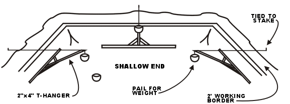
THIS IS NOT NORMALLY NECESSARY: If liner has excessive packaging wrinkles in shallow end, and
won't keep its shape if water was put in, you can make a simple apparatus called a
"T" hanger, which effectively keeps the liner in a pool-like shape but this is
usually not necessary. (See Fig.14). Place cross shaft of the "T" on the liner
in the corner between the panel and the bottom. Be sure there are no sharp splinters on
any part of the apparatus. Hook a plastic bucket of water on a hook on the end of the
shaft, with a cord tied to the hook, lower the "T" shaft and stake the cord to
the lawn.
FIG. 14.
Turn the vacuum on to force the liner into position. It will take 15
to 20 minutes to draw the liner tight against the pool walls. Check for liner leaks.
Once 4 to 6 inches of water are in the hopper it is time to cut the
main drain. The water pressure should be forcing the liner around each screw, thus showing
the exact location of each screw. If the screws were not previously installed the holes
would be difficult to find. Use a Phillips screwdriver in good condition and place it on
top of the screws over the liner. Press downward punching an X mark on the liner. Force
the liner over the screw and remove the screw. Carry out same procedure for the rest of
the drain screws.
CAUTION: DO NOT CUT THE MAIN DRAIN UNTIL THE LINER IS PROPERLY
INSTALLED AND NO FURTHER ADJUSTMENTS ARE NECESSARY. DO NOT PUT WATER
INTO THE POOL UNTIL THE LINER IS PROPERLY FITTED INTO PLACE.
Install drain gasket and ring, with the 8 screws, being careful to put
the screws in straight and tighten down firmly to prevent leaks. Cut out drain liner
carefully with a sharp knife and install drain cover.
Using a standard garden hose, place the hose end in the hopper and start
the water flow. Once there is 6" of water in the hopper, the
remainder of the pool can be filled from the garden hose or a water
truck. DO NOT ALLOW A STRONG STREAM OF WATER TO DIRECTLY HIT THE
POOL BOTTOM.
Continue filling the pool.
The vacuum is normally shut off when you have 3 - 6" in the shallow
end. Wrinkles should be out of the shallow end before 1" of water
covers the area. CAUTION: WATER WILL NOT REMOVE WRINKLES.
When the water reaches 6" to 7" below the skimmer, inlets or light,
cut the holes and install the faceplates. The liner may not be right
back against the steel panel, but the water pressure will force it back later.
Since these pool walls are self-supporting, it is not absolutely
necessary that more backfilling be consistent with the rising water level above the
inlets. Water should be shut off 6" from the coping.
Do not tamp the backfill as excessive tamping can cause distortion in the walls.
GROUNDING THE POOL:
All pools and metal parts (lights, ladder anchors, etc.) should be
grounded. The requirements for grounding will be set by your local
authorities. They vary from region to region so it is best to check
with the offices that issue your building permit.
BACKFILLING THE POOL:
USE
ONLY NON-EXPANSIVE MATERIALS FOR BACKFILL. DO NOT
USE COHESIVE (CLAY) MATERIALS. Excavated materials can be used in low ground frost areas but we recommend a
pit run sand. The advantage of using pit run sand is that it is easier to
work with if future repairs are required. If your backfill material has
large rocks or sharp rock it is advisable to cover your plumbing pipes with
sand. Be careful not to push large rocks on your plumbing pipes as
you may crush them. Do not tamp the back fill as you can bulge the
walls. Do not allow heavy machines ride right next to the pool on the
backfill as the weight of the machine could put too much pressure on the pool
wall and bow in the side.
CONCRETE DECK:
Ensure
the coping clips and joiners are installed over the coping joints. Use duct tape
to completely cover the face of all coping, to protect it from splashing
concrete.
Concrete
should be reinforced with either wire mesh or a fiber mesh additive (available
from most concrete companies).
Concrete
should be a minimum of 6" thick at the pool edge and taper down to about 3
1/2" on the outer edge.
For
proper drainage, the deck should slope a minimum of 1/4" for every 1' of width.
Install
ladder/handrail anchors, as required, when forming deck. All rail goods and
diving board jigs and the pool itself should be grounded (check electrical
codes).
Ensure
concrete completely fills the coping.
Ensure
concrete completely fills the gap under the lip of the step to provide
additional structural support.
Broom
finish the concrete for a non-slip surface or apply other concrete toppings,
such as cool deck.
Edge
and groove expansion joints or use expansion joint material. Do not position
expansion joints directly over the pool wall braces.
Use
additional support (piers) down to undisturbed earth if you do not have deck
bracing.
Pour the deck at least 8' wide
(depending on board size) where diving board
is installed.
INSTALLING THE LADDER:
Assemble the ladder and put the wedge anchors on the ends of the ladder.
Wrap paper around the ladder from the wedge anchors up so you do not get
concrete on the ladder. Ensure the ladder is grounded. Pour
concrete and set ladder in place (wedge anchors go into the concrete). Ensure
the bumpers sit flat on the liner against the pool wall.
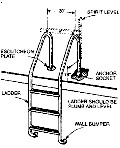 |
Ensure the ladder is level horizontally and
vertically before pouring concrete. The wall bumpers should be
flat against the wall of the pool. Wrap the bottom of the ladder
so when the concrete is poured it will not splash on to the ladder. |
ADDING CHEMICALS AND POOL CARE:
You usually super chlorinate the pool upon start-up, then stabilize,
depending on the brand of chemicals you buy. Then you chlorinate as necessary, depending
once again on brand of chemicals, pool use, severe rain, wind storms, etc. Such factors
can affect chlorine residual and pH of pool water. In addition to following a consistent
water program of chemical use, you should also regularly use a test to check chlorine and
pH levels. Super chlorinate weekly according to outside temperatures and brand of
chemicals. There is also a chemical available to retard evaporation and hold heat in your
pool, cutting heating costs by 30% if you have a pool heater.
Ensure you keep your pool water in balance as it can effect the life of your
liner.
For more information on liner care go to http://www.northwestwholesale.com/liner-care.asp
POOLSIDE GARDENING TIPS
Decide which views you wish to retain and which ones you wish to block out,
keeping in mind the dimensions of the matured plants to ensure that you don't
block desirable views.
To minimize the amount of debris that blows into the pool it may be
helpful to keep in mind the direction of prevailing winds when deciding where to
place the pool.
Low maintenance plantings such as vincas, petunias, dianthus, marigolds
and verbenas are worth considering. Other
recommended plants are ornamental grasses, daylilies, coreopsis and sages.
Because flowering plants will attract bees you may wish to keep them to a
minimum in the immediate pool area.
Container planting, both in pots and hanging baskets, works very well in pool
areas. Bear in mind though
that they dry out quickly and need frequent watering.
Conifers and/or evergreens soften the look of a pool fence and add privacy to
the area. Vines such as
clematis, morning glory or gourds can also be planted against the fence.
Chlorinated water is not good for plants and raised beds may be used to prevent
splashing on them.
Indoor pool situation: Although humidity may seem perfect for tropical plants,
chlorinated air can be harmful to them. The plants should be taken outside as soon as the
weather is warm enough.
SWIMMING POOL WINTERIZING:
Because winterizing methods vary in each part of the country it is best to
get a local pool company to do your first winterizing. Watch what
they do and then do the same the following year.
In areas subject to freezing temperatures, it is advisable to close
the pool down for the winter. The following are a few tips to prevent frost damage to
equipment and structure, and to ensure a minimum of cleaning in the spring.
- Vacuum pool thoroughly so that it is completely clean of all sedimentation,
leaves and debris.
- Backwash filter tank for at least 30 minutes, so that the sand bed is perfectly
clean.
- Lower water level to 2" below inlet openings in wall.
- Add algaecide to remaining pool water according to pool size.
- Close off return fittings by removing threaded ring and directional nozzle and
inserting 1 ½" threaded plug.
- Remove underwater light bulb and store on deck. (Remove screw from chrome plated ring holding
beam in copper niche, disconnect wires in deck box, pull out unit).
- Drain out filter and heater by removing drainage plugs (make sure there is no
blockage at drain plug).
- Remove cover lid from hair and lint strainer, and drain out water by removing
plug at bottom of pump trap.
NOTE: If pump motor is not in shelter, cover with tarpaulin or plastic sheet.
- Remove basket, float valve plate and balancing valve from skimmer. Close trimmer
valve, place burlap sacking in skimmer, holding floating wire in upright position and
replace cover.
- Set gate valve at approximately three-quarters maximum opening.
NOTE: Some installations require no gate valves.
- Set multi-port valve in "winterize" position.
- Remove sight glass and gauges.
Link to Pool or Spa Plumbing Layout
Link to Pool and Spa Plumbing Layout
Link to Solar Heating Plumbing Layout
Link to Pool and Spa and
Ozonator and Chemical Feeder Plumbing Layout
Link to
AquaGenie Layout
Fixing Wrinkles
ENJOY!


